Beyond the Scan: System Design Behind India’s UPI Payment Revolution
Sat Jan 03 2026
The Unified Payments Interface (UPI) processes over 10 billion transactions monthly, representing one of the most sophisticated distributed systems in production today. While users experience seamless 5-second payments, the underlying high-level design reveals advanced distributed systems patterns, microservices orchestration, and real-time API choreography that engineers worldwide study as a reference architecture for building internet-scale platforms.
Architectural Pattern: Federated Microservices with Centralized Orchestration
The Indian UPI architecture implements a hybrid pattern that combines federated service ownership with centralized orchestration. This design choice addresses the fundamental challenge of building an interoperable payment network across competing entities while maintaining consistency and security.
Service Mesh Topology
The UPI ecosystem consists of four distinct service layers:
Layer 1 - Orchestration Layer (NPCI): The NPCI operates the central UPI switch—a high-throughput, stateless routing engine that handles transaction orchestration without maintaining transactional state. This statelessness is critical for achieving sub-second latency at scale, as it eliminates the need for distributed state synchronization across the routing layer.
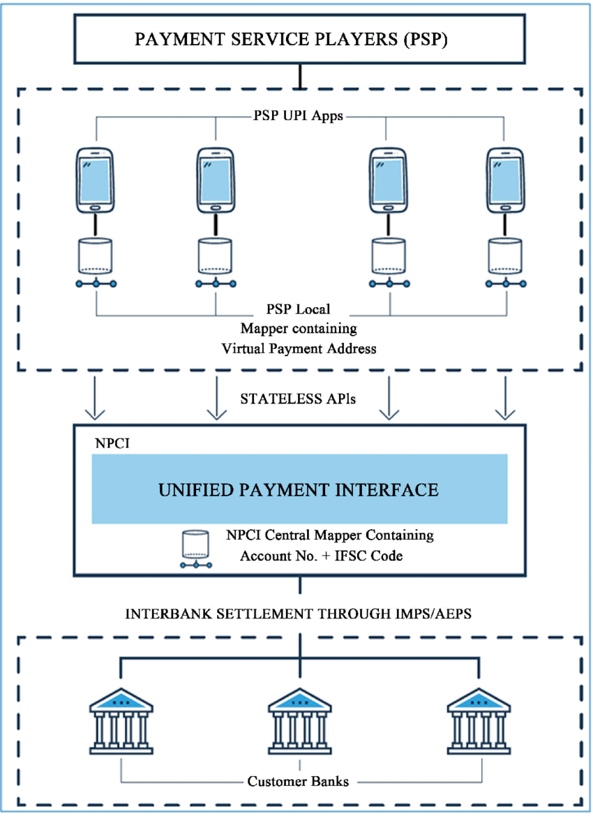
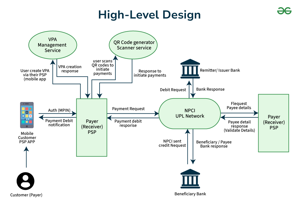
Layer 2 - Application Layer (PSPs/TPAPs): Payment Service Providers like Google Pay implement the presentation layer, handling user onboarding, VPA lifecycle management, and transaction initiation. These services communicate with the orchestration layer via standardized RESTful APIs, enforcing API versioning and backward compatibility contracts.
Layer 3 - Banking Layer (Issuer/Beneficiary Banks): Core banking systems integrate with UPI through adapter services that translate between legacy banking protocols and modern API contracts. This adapter pattern enables gradual modernization without requiring complete banking system overhauls.
Layer 4 - Settlement Layer: Handles the final money movement and reconciliation across the banking network.
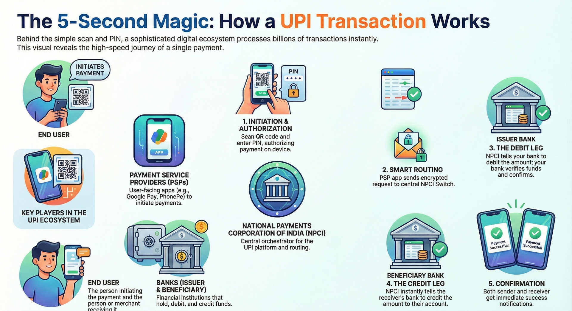
Real-Time Transaction Flow: Distributed Transaction Processing
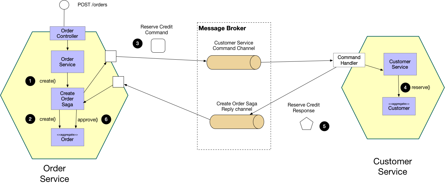
The UPI transaction lifecycle demonstrates a sophisticated implementation of the choreography-based saga pattern for distributed transaction management.
Phase 1: Authentication and Request Construction
The authentication mechanism implements defense-in-depth with multiple security layers:
- Device Binding via SIM Card Integration: During registration, an encrypted SMS establishes cryptographic device binding, creating a hardware-backed security anchor.
- Two-Factor Authentication: Combines possession (device) with knowledge (UPI PIN), where the PIN never leaves the device in plaintext
- Client-Side Encryption: The mandatory NPCI Common Library performs AES-256 encryption on sensitive data before network transmission
The PSP constructs a digitally signed payment request containing transaction metadata (VPA, amount, merchant ID) and forwards it to the NPCI switch over TLS-encrypted channels.
Phase 2: Stateless Routing and Debit Orchestration
The NPCI switch implements intelligent routing using VPA-to-bank mapping tables cached in distributed in-memory data stores like KeyDB. This caching strategy reduces latency from database lookups that would bottleneck at scale.
The switch extracts the payer's bank identifier from the VPA, performs routing table lookups in O(1) time complexity, and forwards the debit request to the issuer bank. Critically, the switch does not hold locks or maintain transaction state—it operates as a pure message router, delegating state management to the banks themselves.
Phase 3: Debit Leg Execution
The issuer bank's adapter service receives the debit request and performs:
- Account validation: Verifying account existence and active status
- Balance verification: Checking sufficient funds using read-committed isolation level queries.
- Atomic debit operation: Executing a database transaction that debits the account and records the transaction log atomically
Upon successful debit, the bank returns a success acknowledgment containing a unique transaction reference number back to the NPCI switch.
Phase 4: Credit Leg Execution
With debit confirmation received, the NPCI switch immediately initiates the credit leg by routing a credit request to the beneficiary bank. The beneficiary bank performs account validation and executes an atomic credit operation.
This two-leg design creates an eventually consistent system where temporary inconsistency (debit succeeded but credit pending) is acceptable because compensating transactions can resolve it.
Phase 5: Asynchronous Notification
Both PSP applications receive success confirmations from NPCI and asynchronously notify users through push notification services, completing the user experience loop.
The SAGA Pattern Implementation: Eventual Consistency at Scale
Traditional distributed transaction protocols like Two-Phase Commit (2PC) provide strong consistency but suffer from critical scalability limitations. In 2PC, a coordinator must lock resources across all participants, creating contention points that degrade throughput under high concurrency.
UPI's architects deliberately chose the SAGA pattern—a long-running transaction model that breaks atomic operations into local transactions with compensating actions. Each service (PSP, issuer bank, beneficiary bank) executes its local transaction independently and publishes events to trigger the next step.
Failure Handling and Compensation
When failures occur mid-transaction, the system executes compensating transactions:
- Debit succeeded, credit failed: A reversal credit request is sent to the issuer bank
- Timeout scenarios: Reconciliation processes detect orphaned transactions and initiate automated resolution
This design trades strict ACID guarantees for BASE (Basically Available, Soft state, Eventual consistency) semantics—a fundamental distributed systems trade-off that enables horizontal scalability.
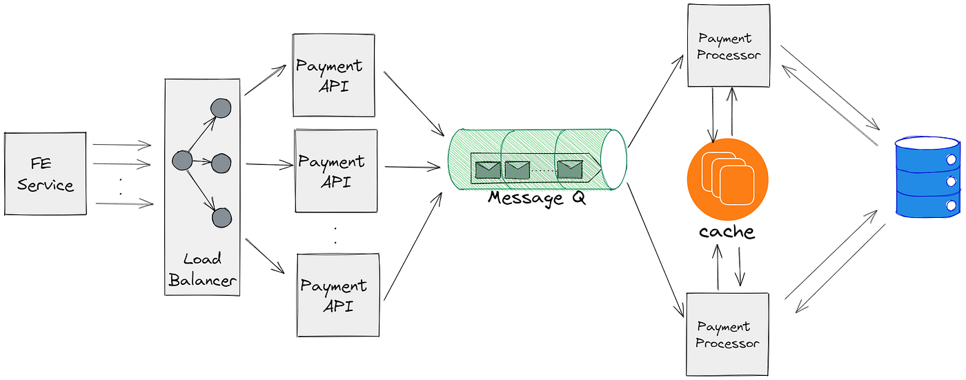
Backend Technology Stack: Polyglot Persistence and Event-Driven Architecture
The UPI backend implements polyglot persistence—using specialized databases optimized for specific access patterns.
Data Store Architecture
Apache Cassandra (NoSQL): Handles high-velocity transaction writes with tunable consistency levels. Cassandra's leaderless replication and partition tolerance make it ideal for storing billions of transaction records across geo-distributed data centers.
PostgreSQL/MariaDB (RDBMS): Stores structured relational data requiring strong consistency—user profiles, account mappings, and audit logs. These databases support complex JOIN operations and maintain ACID guarantees for critical financial data.
KeyDB (In-Memory Cache): A Redis-compatible cache storing hot data like VPA-to-bank mappings, session tokens, and rate-limiting counters. Sub-millisecond read latencies from RAM dramatically reduce backend load.
Event Streaming with Apache Kafka
Kafka serves as the event backbone, implementing publish-subscribe patterns for asynchronous communication between microservices. Transaction events flow through Kafka topics, enabling:
- Event sourcing: Maintaining complete audit trails of state changes
- Real-time analytics: Stream processing for fraud detection and monitoring
- Decoupled service communication: Services react to events without tight coupling
This event-driven architecture enables the choreography-based saga implementation, where services listen for events and trigger their local transactions accordingly.
Infrastructure: Cloud-Native Design with Kubernetes Orchestration
The platform runs on Kubernetes clusters orchestrated across multiple availability zones. Kubernetes provides:
Auto-scaling: Horizontal Pod Autoscalers dynamically adjust service replicas based on CPU/memory metrics and custom metrics like request latency
Service mesh integration: Traffic management, circuit breaking, and retry logic implemented at the infrastructure layer
Rolling deployments: Zero-downtime updates using blue-green or canary deployment strategies
Container orchestration with Kubernetes represents modern cloud-native practices, enabling automated failover and handling India's massive diurnal traffic patterns.
Observability Architecture: The Three Pillars
Production observability implements the three-pillar model:
Distributed Tracing
Each transaction receives a unique trace ID propagated through all service hops, enabling end-to-end latency analysis and bottleneck identification.
Metrics Collection (Prometheus)
Time-series metrics track RED (Rate, Errors, Duration) indicators for each microservice, with alerting thresholds triggering incident response workflows.
Structured Logging (Fluent Bit)
JSON-structured logs enriched with contextual metadata (merchant ID, geographic codes) enable rapid debugging and compliance auditing. The shift from batch log processing to real-time log streaming was essential for meeting SLA requirements.
Reconciliation: The Financial Consistency Layer
Automated reconciliation processes run four times daily, implementing a batch settlement system that detects discrepancies between NPCI's transaction logs and bank ledgers. This multi-phase reconciliation acts as the eventual consistency guarantee, ensuring financial accuracy despite the distributed nature of transaction processing.
System Design Lessons from UPI Architecture
The Indian payment gateway demonstrates several advanced distributed systems principles:
- Stateless routing layers enable horizontal scalability
- Polyglot persistence optimizes for diverse access patterns
- Eventual consistency trades CAP theorem guarantees for availability and partition tolerance
- Event-driven choreography reduces coupling in microservices
- Mandatory security libraries ensure uniform cryptographic standards
For system design interviews and real-world architecture: Study UPI's approach to distributed transactions, its compensating transaction patterns, and how it achieves 99.99% availability through redundancy, circuit breakers, and graceful degradation. This architecture represents production-grade distributed systems engineering at internet scale.
🔗 Related Articles You May Like
If you enjoyed this deep dive into system design and high-level architecture, you might find these articles useful as well:
- 🔮 Coding in 2026: What Engineers Must Prepare For
A forward-looking guide on how AI, automation, and system-level thinking will reshape software development.
👉 https://www.thesgn.blog/blog/coding2026 - ⚡ VS Code vs Zed: Choosing the Right Editor for Modern Developers
A practical comparison of developer tools, performance, and workflows for today’s engineers.
👉 https://www.thesgn.blog/blog/vscode_zed - 📚 Best Computer Science Books Every Developer Should Read
A curated list of foundational CS books that strengthen problem-solving and system thinking.
👉 https://www.thesgn.blog/blog/csbook - 🏢 CRM Solutions for Business: A System Design Perspective
How scalable CRM systems are built and why architecture matters for growing businesses.
👉 https://www.thesgn.blog/blog/CRM_solutions_for_business